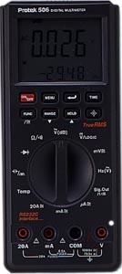
The basic electronic measuring tool is the meter. The most common meter is called a multimeter, and will measure voltage, current and resistance. Inexpensive meters are analog, meaning they have a moving needle and usually a lot of scales to decode. Newer designs are digital, with more features and an easy to read display:
Analog or digital, the basic use of the meters is the same. You have to set a switch to choose the function, and sometimes move the leads to a particular hole. You may also have to select the range (highest value you expect to measure), but many meters are auto ranging.
To measure voltage, leads must be placed across components. Remember, the ground symbol indicates the 0 volt reference point for the circuit- usually the black or negative lead of the meter is placed here.
To measure current, you must break the circuit and run the current through the meter.
To measure resistance, the component must be completely removed from the circuit.
To measure continuity, measure resistance and look for nearly 0 ohms. Some meters beep when 0 ohms is found.
To measure capacitance, you need a special meter. The component must be out of the circuit.
It's pretty easy to damage a meter by trying to measure too much current, so there's probably a fuse in it. Read the instruction booklet all the way through.
AC is always more difficult than DC, and that's certainly true when taking measurements. If you measure the voltage of a changing wave, you really want some kind of average amplitude. (The actual average voltage of a waveform is likely to be 0, since it swings both positive and negative.) The AC positions on the multimeters add some circuitry to make the reading more useful.
There are four possible measurements to be made on a waveform-
RMS is properly determined by sampling the voltage, squaring those numbers, finding the mean of those numbers, then taking the square root of the result. This is done properly by digital meters but just approximately by analog meters, which will give accurate reading only on sine waves. A digital meter should give true RMS on any waveform.
There are usually two inputs. Inside the scope is a circuit called the "time base generator" that moves a dot across the screen. There's a control to set how fast the dot moves, usually marked in milliseconds per centimeter. A typical screen is 10 cm across, so a 0.1 ms/cm setting is appropriate to show a 1khz tone.
As the dot is moved across the screen, the voltage at the input moves the dot up and down. There is an input gain switch to adjust how far, calibrated in volts/cm. The result may look like this:
You can read the voltage and frequency of the waveform by looking at the markings on the screen and the settings of the time base and gain switches.
If the waveform is periodic, you can turn on "triggering" which will synchronize the timebase with the waveform. There are switches and knobs to set exactly how the triggering works (Sometimes "not triggered" is called "autotriggered". When this is on, the display creeps or rolls across the screen.)
If the scope has two inputs, you can compare two waveforms, such as input and output. Sometimes you can use the two inputs in X-Y mode, where the timebase is shut off and one input moves the dot from side to side. This gives lissajous figures, which can be lovely geometric forms with simple waveforms, but will just be a scribble with real music. They can still be informative though- if the two inputs are out of phase, you will see circles in the patterns.
pqe 10/9/98