WHAT TO DO WITH YOUR SYNTHESIZER
[We still study analog synthesizers for two reasons: they are capable of things that can't be done with most digital machines available today, and their operation is the model that digital systems (and their manuals) are based on. They are also a lot of fun. (OK three reasons.)]
Analog Synthesizers were made by many people and companies. We have several examples at UCSC, including:
A Moog Synthesizer
An Emu Modular
A Synton
A homemade machine
A studio synthesizer is a collection of boxes (referred to as "modules") each of which has its own simple function. The modules must be connected together with patch cords before any sound can be made. This patching requirement makes the synthesizer a rather difficult instrument to learn but also gives it a tremendous range of sounds.
The sound of a patch depends on the interconnection of these modules and on the settings of their knobs.
The patching process is best understood if you keep in mind the kinds of information that are transmitted by the various patch cords.
Some cords carry the electrical version of the sound we will eventually hear. This is the SIGNAL.
Some cords carry instructions to modules about how to change the signal. These are CONTROLS.
Some cords carry instructions about when modules should start their functions. These are TRIGGERS and GATES.
It is also very useful to keep in mind the kinds of functions the modules can perform. Most patches will involve at least one module from each group.
Modules which can originate a signal are called SOURCES. The most common of these are oscillators and noise generators.
Modules that can modify a signal are called PROCESSORS. The most common examples of these are amplifiers and filters.
Modules that produce only controls and triggers are called CONTROLLERS. Controllers may be preset, such as envelope generators and low frequency oscilators, or they may be playable, like keyboards.
The following sections give generic descriptions of the most common modules.
5.1 THE MOST LIKELY MODULES
OSCILLATORS
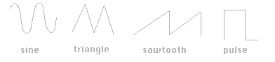
The oscillator, or vco (for voltage controlled oscillator) is the most commonly used source module. It generates a steady signal at a preset pitch. The signal is usually available in a variety of waveforms (sine, triangular, ramp, and square are the basic ones.) that are selected by the patch connection. The initial pitch is adjusted by two knobs on the module, one with a wide range, another for fine tuning.
The most important input to the module is the frequency control, also called FM in. A voltage applied to this jack causes the pitch of the oscillator to rise, usually at the rate of one octave per volt. This function is important enough that there are often two or three such jacks. The resulting pitch is always established by the sum of all such input voltages. A negative voltage will of course cause the pitch to go down.
On some models pitch control inputs are provided that have an effect different from one octave per volt. This might be linear (each volt adds perhaps 10hz), or have a knob (an attenuator) that reduces the amplitude of the control voltage.
If the oscillator features a pulse output, there will be a way to modify the duty cycle of the pulse. (A pulse wave is high part of the time and low part of the time. The duty cycle is the ratio of the high part to the whole period of the waveform.) There will be a knob and sometimes a control input for this function.
The Basic Voltage Controlled Oscillator Waveforms.
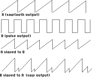
Many oscillators have an input labeled SYNC. This function allows an oscillator to lock its pitch to the output of another oscillator. When this is done the connection goes from the pulse output of one oscillator (called the "master") to the sync input of another (called the slave). The pitch of the slave will follow that of the master, unless the master goes lower in frequency than the slave is set. When that happens the output of the slave will either jump to harmonics of the master or give a mix of both pitches. The output of the slave is distorted in any case.
Oscillators are not always used to generate signals. They are also a good source of control voltages, generally used at sub-audio rates. Because it is difficult enough to build an oscillator with the ten octave range necessary for signal sources, special low frequency oscillators (LFOs) are often provided for this. The fanciest of oscillators have a switch that sets them to the sub-audio range.
[Digital systems may call their equivalant of an oscillator DCOs or just oscillators. Sample based systems refer to the the tone, waveform, or insstrument. Same thing, slightly different approach.]
AMPLIFIERS
The amplifier is a processor that changes the amplitude of a signal.
The knob adjusts the loudness from off to full blast. (Perversely, very few systems have amplifiers that increase the signal level beyond that provided by the oscillators. We should really call them voltage controlled attenuators.) A voltage applied to the control input increases the level of the output, either logarithmically (10dB per volt) or linearly. The response function may be selected by a switch or by the choice of control jacks.
Amplifiers usually have a very wide frequency response, from DC (so they may process controls) to the top of the audio range.
Amplifiers are the basic tool for adding envelopes to sounds. They are so useful and cheap that you often find them built into other modules for complex features like voltage controlled portamento on an oscillator.
Action of Voltage Controlled Amplifier
[Amplifiers per se are not mentioned much in digital systems. The closest we see is MIDI volume. Everything has level or volume as a destination for the LFO and envelopes though.]
FILTERS
Because the palette of sound from the oscillators is rather limited, most of the sound flexibility of a synthesizer comes from the filters. Three basic kinds of filter are present, low pass, high pass, and multi-mode. All have panel and voltage control of the cutoff frequency, which may be anywhere in the audio range. The cutoff slope of the filter may be partially adjustable with a "Q" control, but it will be rather steep in any case.
LOW PASS FILTERS remove all parts of the signal above the cutoff frequency. Remember this cutoff is not absolute but follows a curve, usually 24dB per octave. Turning up the Q (sometimes called resonance) control exaggerates any signal near the cutoff frequency. In fact many filters will oscillate at the cutoff frequency if Q is set very high. Low pass filters are often used like amplifiers, for shutting off (or "gating") a signal.
HIGH PASS FILTERS are the complement to the low pass in every way. They remove all parts of the signal lower that the cutoff frequency. You often find both high pass and low pass filters on the same panel to provide bandpass or notch functions.
MULTI-MODE FILTERS combine several functions at the expense of the sharp cutoffs found in the single function designs. You get low pass, high pass and bandpass outputs, each from its own jack. There is also often a notch output available. The q on these filters can usually be turned very high without oscillation, although they will "ring" at the cutoff frequency when pulse type inputs are applied.
FILTER BANKS are graphic EQs built into a module. They are useful for subtle timbre effects, like applying formants to a sound.
[Very few digital systems have filters that are as interesting as the old analog modules. Digital filters are hard to program.]
ENVELOPE GENERATORS
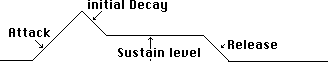
An envelope generator produces a control voltage that rises and falls once, according to a voltage command. When a command is applied, the output rises to full on and then falls to zero. There are knobs to set the time the output takes to rise and fall, called ATTACK and RELEASE. Because of the attack and release functions, such a device is often called an AR.
An ADSR type envelope generator responds to a command in the same way as the AR type, but the result is more complex. The output goes to a maximum value at the rate set by the ATTACK, but immediately falls to some intermediate voltage at rate set by a knob called DECAY. The value of the intermediate voltage is set by the SUSTAIN knob. The sustain phase can last as long as desired. The time for the final fall to zero is set by the RELEASE control.
Features sometimes added to envelope generators include voltage control of some parameters, delayed start, and end of release pulses. Many also include a light that tells when the generator is operating.
The form of the command that starts the envelope varies from one make of synthesizer to another. The most common is a voltage that rises from zero to five volts and stays at that level until the end of the sustain period. It is the drop of that voltage back to zero that initiates the release phase of the envelope. This relatively long duration pulse is often called a gate. A very short pulse is usually called a trigger, and performs a variety of timing functions.
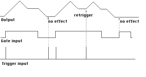
Some envelope generators feature two timing inputs, GATE and TRIGGER. On these models, the trigger starts the envelope process and the gate determines the length of the sustain phase. Usually, both inputs must be present for normal operation. The retrigger function provides a natural articulation during keyboard performance, if the keyboard supplies a trigger pulse whenever a new key is pushed.
KEYBOARDS
A synthesizer keyboard may look much like an organ keyboard, but it functions quite diferently. The typical keyboard gives a constant control voltage output corresponding to the last key pressed. This output is usually one volt per octave, but the actual relationship between key pushes and pitches depends entirely on the patch. Note that this is a monophonic beast. If there is a second voltage output, it usually corresponds to the difference between two keys pushed at the same time.
Keyboards also supply triggers and/or gates for starting envelope generators. A trigger is a brief pulse denoting the start of an event (in this case a key push). A gate is an extended pulse that corresponds to the length of an event (a key held down). Keyboards usually give both so you can get definite starts to tones even if you fail to release one key before pushing another. (The gate just stays on when that happens.)
Most keybords have a portamento feature, meaning the output can glide from one voltage to another instead of changing abruptly. There will be a knob to control this.
Most keyboards have tuning and transposing adjustments also.
5.2 MORE MODULES
The modules already described allow the most basic operations, such as keyboard performance. More modules increase the possible functions or add variety to the basic sounds.
NOISE GENERATOR
This is the simplest module on the machine. It produces a steady hiss that is a useful basis for some non-pitched sounds. There may be a choice of white or pink noise, or even a species of low frequency noise for random control voltages.
RING MODULATOR
This is a delibrately bad amplifier. When two signals are combined in this device, the output is pure distortion (sum and differences of the frequencies of the two signals) with all remnants of the original signals carefully removed. The resultant sound is usually quite non-harmonic.
MIXERS
All synthesizers have some simple mixers to allow the combination of signals. There will be level controls on some of the inputs, but not necessarily all of them. Mixers are cheap enough that they are often built into modules with other basic functions..
SEQUENCER
Sequencers allow you to preprogram a tune (a series of voltages anyway) with a set of knobs. Usually the tune repeats as an ostinato. Sequencers are seldom found as modules any more as they may be replaced by very simple computer programs.
SAMPLE AND HOLD
The sample and hold module was originally developed to be a cheap alternative to a sequencer (all those knobs are expensive). Its basic function is to capture a momentary voltage and keep that voltage at its output until told to sample again. (Keyboards contain this circuit as a matter of course.) If you sample a steady waveform at a slow rate (aliasing) a variety of repeating patterns will emerge that depend on the precise relationship of the two frequencies involved. If you sample noise, you get a totally random output.
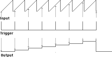
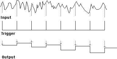
Most sample and hold devices have a dedicated low frequency pulse oscillator (called a clock) to provide steady triggers.
[Digital systems that claim to have a "Sample and Hold" effect (usually an option for the LFO really produce random steps at a steady rate.]
CONTROL PROCESSORS
There are a variety of processors that are meant to transform control voltages rather than audio signals. They are variations on the basic processors designed to be effective at low frequencies.
ATTENUATORS simply reduce the level of a voltage. These may be built into other modules rather than alone. This is the only module that works when the power is off.
INVERTERS change positive voltages into negative ones. This is useful for generating contrary motion from a keyboard or gating sounds with a high pass filter.
A REVERSABLE ATTENUATER performs both of the preceeding functions at the same time. It has a single knob; if the knob is fully clockwise, the control voltage is unchanged. As the knob is turned back, the amplitude is reduced, becoming zero when the knob is centered. As the knob is turned further to the right, the amplitude again increases, but now in inverted form. When the knob is fully counterclockwise, the output is an exact inversion of the input.
LAG PROCESSORS slow down the change from one voltage level to another (this is a super low pass filter). The circuit that produces the portamento output of the keyboard is an example. You may get separate controls for up and down.
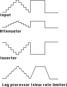
Output of control processors.
INTERFACES
Interfacing is connecting the synthesizer to the outside world. This is necessary electrically because the signal levels in the patch cords are somewhat higher than those used in other audio devices.
• PREAMPLIFIERS allow the connection of the outputs of standard audio devices to the machine. These can include microphones, guitar pickups or line level signals, depending on the setting of the gain control.
• OUTPUT BUFFERS reduce the output of the synthesizer to line level so it will not blow out speakers and ears. They may function as the master volume control, or they may have a calibrated output level. Please note that continous very high frequency tones are hard on speakers even at rather low amplitudes.
• ENVELOPE FOLLOWERS translate the amplitude of a signal into a control voltage. This allows you to superimpose the envelope of some existing sound onto a waveform produced by the synthesizer.
• PITCH FOLLOWERS translate the frequency of a signal into a control voltage. This makes it possible to use any single pitch producing instrument to control the machine.
MECHANICAL TRANSDUCERS
There are a multitude of ways to connect the performer to the instrument other than the traditional keyboard. All produce control voltages according to the manipulation of some device, for example:
Joystick
Breath pressure gauge
Temperature sensor
sonar detector
Touch plates (ribbon or x-y)
Proximity detector (theremin style)
Foot pedal
Trumpet valves
Scales (the kind that weigh things)
Optical sensors
and probably many more.
5.3 PATCHES
GETTING A SOUND OUT OF THE SYNTHESIZER.
Turn the synthesizer power on before you make any connections.
A modular synthesizer will make no sounds until the modules are patched into some sensible configuration. Patching on the unit is performed with the patch cords kept on a rack by the machine. The cords for the Synton and Kludgephone (the homemade synth in 133) have bannana plugs on them Bannana plugs are used for these two because the signal levels within the synthesizers are rather high (20 dB hotter than the patch bay). Never attempt to connect an unbuffered bannana plug signal directly to the other equipment; follow the procedures described here in making connections:
SYNTON: There are four output lines at the lower left of the synthesizer. These lines are internally buffered and connected to the studio patch bay. To hear a sound, connect the output of the last module in your patch to one of these lines and patch from the appropriate jack on the patch bay (Synton out 1-4) to the mixer, monitor or tape deck.
Moog: there are two jacks near the keyboard outputs labeled trunk lines. These run directly to the patchbay and may be used for input or output.
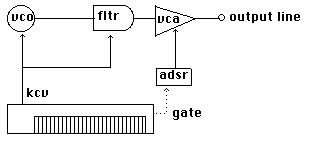
BASIC KEYBOARD PATCH
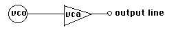
All patches must start with a source, such as an oscillator. You should always test your monitor hook up with an oscillator straight out. Experiment with the various outputs of the oscillator to get a feel for the raw sound.

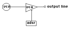
Soon you will want to turn the oscillator off. The processor appropriate for turning things off is the amplifier (vca). Patch osc out to vca audio in, amp out to monitor. Experiment with the various knobs to see which turn the sound off.
The most common control hook up is envelope generator to vca. Patch the output of the eg to the control input of the vca. Remember that the envelope generator can only have indirect effects on sounds, by controlling other modules. Fire the eg with the button or switch and experiment with the knob settings. You should be able to get a wide variety of sounds with these controls.
Now hook up the keyboard.
SYNTON: Connect kbvc to the oscillator fm input, and the keyboard gate output to the envelope generator trigger input.
MOOG: Connect keyboard 1 out to the control in of the oscillator. There are special two prong plugs to connect Keyboard Trigger to the envelope generator.
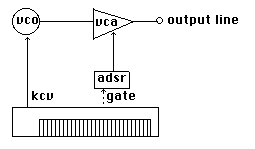
Now you should be ready to play tunes.
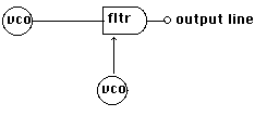
5.31 FILTERING
There are three basic ways filters are used; static, dynamic, or for gating.
For STATIC use the filter is patched before the vca in the signal path. The filter is carefully tuned (both frequency and resonance) to provide the timbre desired, but not voltage controlled. This provides a timbre that varies according to pitch, a feature of most natural instruments.
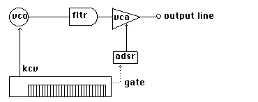
For DYNAMIC use the filter is controlled by the same device that is controlling the pitch. This will produce the same harmonic structure on each note, regardless of pitch.
In GATING, the filter is used to replace the vca, under control of the envelope generator. If low pass, the filter is tuned lower than the oscillator to shut the sound off. When the envelope generator is fired there will be a sound which will vary wildly according to the settings of the filter and eg. If a high pass filter is used,it is tuned to the top of the audio range and the envelope is inverted. It is often necessary to follow the high pass filter with a low pass to ensure that the sound is cut off completely. Band pass filters used this way give interesting effects but do not cut off the sound, so they need to be followed by a vca.

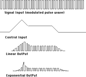
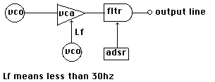
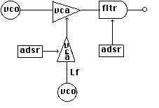
5.32 MODULATION
Modulation means change. In electronic music we use the word to refer to changes in some parameter made at an audio rate. There are four common flavors of modulation, all of which can produce striking non-harmonic sounds. In each case the effect is produced by patching the output of an audio oscillator to the control input of the appropriate device.
FREQUENCY MODULATION produces a very rich spectrum of sound, which may or may not have a definite pitch, depending on the relationship of the frequencies involved. The higher the amplitude of the modulating signal, the messier the sound.
AMPLITUDE MODULATION produces a sound consisting of the two original signals, plus new partials equal in frequency to the sum of and difference between the originals.
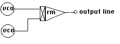
RING MODULATION is a special case of amplitude modulation that give the sum and difference tones without any of the original signals. (Ring modulation is accomplished with a specialized module.)
FILTER MODULATION gives a sound no one has yet managed to analyze. It can best be described as a frenzied bubbling, or the chirping of a thousand angry crickets.
5.33 VCA TRICKS
It's very common to use vcas in the manner described in the basic keyboard patch, turning the signal off to get some peace and quiet between notes. Vcas are also very useful for subtle effects that involve processing the control voltages.
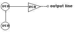
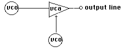
For instance when amplitude modulation was demonstrated, it was shown to be an extreme case of (amplitude) vibrato as in this patch.
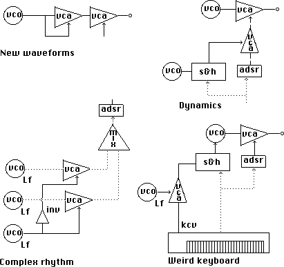
If we add a second vca and eg to the modulating signal, we get a vibrato that varies over the length of the note. This feature can be added to any of the modulations for a process refered to as DYNAMIC MODULATION.
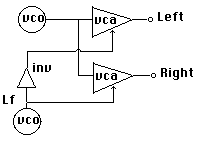
Going back to vibrato, if we use two vcas in parallel, and control one with the inversion of the control used on the other, we can get a continuing pan effect.
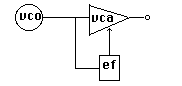
If we put the vca back in the signal path, but get the control voltage from
an envelope follower before the vca, we have created an expander.
Here are some more of the amazing things that can be done with vcas.
5.34 THE SAMPLE AND HOLD AT WORK AND AT PLAY
Look back at section 5.2 for a diagram of what a sample and hold does. The output is a step-like control voltage that depends on the nature of the input and the relationship of the input frequency (if any) to the clock rate. Here are the general rules:
If the input is noise, the output is random.
If the input is a waveform with a rate slower than half the clock rate, the output will resemble the input (in steps of course).
If the input is a waveform with a frequency faster than the clock rate, the output will go in patterns that suggest the shape of the input waveform, but may be backwards or scrambled. (It is possible to get an unchanging output this way.)
To find uses for the S&H, we might consider the most common shapes for controls and their uses. Controls may be stepwise and discrete, like the output of the keyboard (portamento off), or sloping, like the output of an ADSR. We usually use discrete voltages for pitches and "preset" kinds of timbre change. Sloping values are good for envelopes and unpitched (or at least untuned) events.
One thing the S&H does is turn a sloping change into a discrete one, so generation of pitches comes quickly to mind.
The easiest thing to do is indeed to generate a set of funny pitches, using the internal clock to provide a steady rhythm. We also want to syncronize the S&H sample with an ADSR to get clean notes. This is done with the clock trigger out. (Synton users can do this by connecting the ext INPUT to the comparator input. The comparator output is a useful trigger.)
There is a small problem with some S&H designs: they let a little bit of the input signal leak through while they are sampling. This causes a glitch as the voltage changes, but the glitch is kept inaudibly short by making the pulse width of the clock very narrow. If you should want to use an external trigger to get a more interesting rhythm (and you should), you must make the pulse you are using very narrow. If the LFO you want to use does not have variable pulse width, make it using the triangle output and a comparator. If you still can't get rid of the glitch, invert the trigger on the way to the ADSR and turn the sustain off.
Here are some other interesting things to try with the S&H:
Control a filter, sampling noise and triggering with the keyboard.
Control modulation depth (see sec 5.33) of any kind of modulation.
Control pulse width of an oscillator. Use that pulse to trigger an ADSR and the S&H.
5.35 Using Sequencers
Sequencers were the predecessors to the computer controlled systems we use now. These modules always have lots of knobs arranged in rows and columns. There is an output jack at the end (usually ) of each row. One column is active at a time. The voltage at the jacks is determined by the corresponding knob in the active column. There were a bewildering variety of sequencers built, all with different and surprisingly advanced features. The largest I have heard of had 100 columns.
The active column changes when a pulse is applied to a jack on the sequencer. Since this pulse is usuallly a steady thing, it is called the Clock. Typicallly, the clock also triggers an envelope generator so the start of notes is synchronized with the changing pitches.
Sequencers are most useful for generating patterns of notes. The trick is to find patterns that do not get boring too fast. There are two problems to attack, rock steady rhythm and exact repetition of the pitches.
There are three common approaches to changing the rhythm:
• Use a voltage controlled oscillator as the clock source, and modulate its rate. That will change the timing independently of the sequence.
• Use one of the sequencer rows to control the rate of the clock. That way each note has its own duration.
• Don't trigger the envelope generator with the clock- trigger it with the individual trigger outputs of the columns. That will give irregular patterns, maybe two independent voices. You may have to mix the triggers to do this.
Here are three ways to get more interesting patterns of pitches:
• Skip stages and change direction. This depends on the feature of the individual sequencer. Some of them got quite elaborate this way.
• Use more than one row to control pitch by switching the voltages around. This may be a feature of the sequencer or require a special module.
• Use more than one sequencer to control the pitch of the same oscillator. Two sequencers with different lengths will give patterns that are fractal like, going a long time without repeating exactly.
Generating patterns of notes is just the beginning. Try these:
• Use a very slow clock, and patch the sequencer to turn on different sections of a complex patch- that way the sequencer is controlling form.
• Run the sequencer at audio frequency and listen to it. Turning the knobs will change the waveform. You can even use it as a signal processor this way.
• Clock the sequencer with the keyboard.
• Set the sequencer to stop at the end (use the hold feature of the Serge), then hit various stage buttons or pads.
• Retune the knobs as the sequence is playing.
• Clock the sequencer with the envelope follower. If you follow a click track recorded on the ADAT you can build up very complex but synchronized textures.