
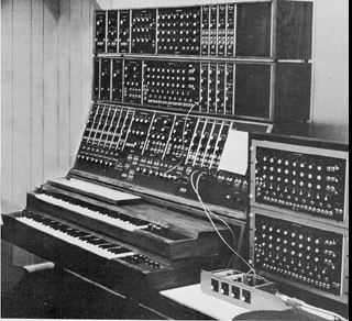
A large Moog system circa 1970, from Moog sales literature.
This page mainly describes the UCSC Modular Moog, one that
is on the small side, but is representative of most studio machines.
Eventually I will add notes about modules we don't happen to have
here.
pqe
Moog synthesizers were custom assembled for each order. There were two types of case, a nice looking wooden console, and a portable box covered in black crinkly paper. There were some standard setups, but most studios chose their modules a la carte. Prices in 1969 ranged from $125 for an envelope generator through 395 for an oscillator to 1,225 for a sequencer. (At that time a hamburger cost fifteen cents.) The order form included a map so you could specify where you wanted your modules, but they could easily be moved around. Almost all of us bought only a few modules at a time, and many systems still have empty space. This is how ours is laid out
Each module is a self contained electronic device. There are practically no connections built into the system: nothing will happen until you patch some modules together. This patching is done with cords of awkward length terminated with 1/4 in phone plugs.
Modules fill one of three types of function:
The patch cords that run from module to module carry one of three types of information:
There is little electrical distinction among module types. An oscillator output may be used as a signal, or a control, or trigger events.
There is no right or wrong way to use the Moog-- no combination of cords or knob settings can damage it in any way. Of course some patches won't make any sound and are therefore of limited use.
Unlike many other synthesizers, the signal outputs of each Moog module are of appropriate level to connect directly to other audio equipment. A typical setup would have "trunk lines" running from various parts of the Moog to the patch bay. (A trunk line is simply a wire connecting two jacks. You may run signals either way along it.) A good way to use these is to connect the output of the mixer module to line 1(above the power switch), and connect Moog line 1 (at the patch bay) to the mixer. Arrange your patches to pass through the mix module and you will have convenient control of all sound.
To process a signal from the studio, connect it to Moog line 2, and connect trunk line 2 (left box, above the power switch) to the preamp or envelope follower.
You can't. For best results (Funky but usable) set the fixed control voltage and control voltage vernier at 0 and the Frequency range at 8 or 4. Patch from the voltage out of the keyboard to the control input of the oscillator. Hit the lowest key repeatedly as you adjust the Range control of the keyboard so that the oscillator pitch is not changed. (Pull the patch cord to check.) Now play octaves and adjust the keyboard Scale knob until things sound right.
 This is two (or more) oscillators
which share a controller section. They may be tuned to any interval,
and any control voltage applied will change the pitch of all keeping
the intervals the same.
This is two (or more) oscillators
which share a controller section. They may be tuned to any interval,
and any control voltage applied will change the pitch of all keeping
the intervals the same.
Start with fixed control voltage on the A unit at 0 and use the frequency range and vernier on the b units to set the desired interval.
Pitch is reasonably accurate as long as the total of all control voltages is under 5 volts.
Eventually, the 901 oscillators were replaced by the 921 models. These were pretty much the same, but had better frequency stability.

This amplifier is differential, meaning it is the difference between the upper and lower signal input that is amplified. Furthermore, the upper output is inverted relative to the lower, so if you want a signal (or control voltage) to come throug uninverted, input it on the upper and take it out the lower, or vice versa.
The control may be either exponential or linear, depending on the setting of the switch. In either position, the amp is full on when 6 volts (total) is applied. This doubles whatever signal is input. In exponential mode the signal decreases 12 db for each volt below 6. In linear mode the signal amplitude is porportional to the control voltage.
This produces an ADSR type envelope, except here it's called T1,T2,Esustain,T3. Notice that the T3 time begins when the trigger voltage goes up.
The Moog has two types of trigger. An "S-trig" is generated by the keyboard and recognized by the envelope generator. There is a special patch cord for S-trigs, with a two bladed plug. (If you short the two input blades together, the envelope generator will fire).
A "V-trig" is a pulse similar to those put out by the oscillators. The sequencer needs V-trigs as clock or trigger inputs and produces them as trigger outputs. There are special patch cords that convert V-trigs into Strigs.
The 904 series includes two kinds of filter module, the 904A low pass and the 904B High pass. There is a third module, the 904c coupler that mixes the output of the the two functions.
If you only want a low pass or high pass function, set the switch on the coupler to off. Otherwise you will find the filters hard to adjust. Note there is frequency range switch, just like on the oscillators.
If you set the coupler for band pass, a signal patched to the coupler input will be applied to the highpass section, then that output is applied to the lowpass section. This produces the bandpass effect. At the same time, the controls labeled center frequency and a voltage controlled by the center frequency knob are connected to both filters so that they will change toghether. The Bandwidth jack and knob are also connected to both, but in such a way that the low pass frequency will go down when the high pass frequency goes up.
The band reject is similar, except the two filters are in parallel.
When you are coupling the filters you still have to carefully adjust the initial frequency of each to get the result you want.
The 907 Filter Bank is a graphic eq with knobs instead of sliders.
The sequencer provides a series of control voltages. One of the eight stages is active at a time, as indicated by the lights across the top. When the shift input is pulsed, or the internal oscillator fires, the next (right) stage is activated. A press on the Shift button will also step the sequence.
Each stage is a column of three knobs, two jacks and some switches. When a stage is active, its knobs determine the voltage at the output jacks toward the right side of the panel. For each of the three rows of knobs there is a pair of jacks and a switch that multiplies the output times 1, 2 or 4. The maximum output is 8 volts.
Each stage has an In and Out jack. The Out jack goes high (about 3.5 volts) when the stage is on. A V-trig at the in jack turns the stage on, as does a push on the Set button. The three position switch controls the sequencing: in Skip position, this stage will not be turned on. In Stop positon, the sequence will stop at this stage.
There is a "stage nine" that has only the switch and jacks, no knobs. Normally the stage is skipped (there's no normal position on the switch). If the the switch is set to stop, the sequence will end there with all outputs at 0 volts, and the internal oscillator will be turned off.
The internal oscillator is very similar to the 901 modules but is designed to run very slow, and only produces V-trig type pulses. Frequency range, vernier, and control input are the same. It has and "on and off" feature. A light indicates when it is running, and it can be started and stopped with button presses or V-trigs at the input jacks.
The "Third Row to Timing" switch connects the output of row C to the control input of the internal oscillator. A knob turned up on row C will then shorten the time spent on that stage.
There are special patch cords to convert the V-trig output of the internal oscillator (or any stage output) to S-trigs to fire the envelope generators.
It's possible for more than one stage to be on at once, actually. One way to make this happen is to patch the output of one stage to the input of another. To get back to only one stage on, push a set button.
Most Moog systems feature a few homemade additions. These provide functions that were not available in the original series. Hotrodding Moogs is a whole topic in itself: it's a delicate balance bewteen fixing glaring problems and keeping the essential Moog sound.
These particular modules are unique to the UCSC setup, but are typical of what you might find.They are all simple to construct using modern ICs
Moog assumed that being able to run the 901 oscillators at subaudio rates would give enough LFO type control. However, that is a very expensive approach, and the 901s don't have enough output to do the more extreme effects like wide range filter sweeping.
There are two outputs; pulse is different from the 901s in that the on time is independent of the rate. This gives independent control of note durations. If the duration is set longer than the period of the LFO, notes will be skipped. The other output has a switchable shape and adjustable level.
This module has three sample and hold circuits on it. Sample and hold was never a Moog thing, it was first found on Buchla synthesizers and then on just about every second generation system.
The ouput of section one is normalled to section two, and section two is normalled to section three. This way a voltage is passed from one section to another to give sort of fugal effect.

The functions of this module were originally provided by classic studio equipment
 This is a simple stereo mixer,
4 inputs, with gain and pan controls for each. Usually, this will
be the final module in a patch, with the outputs taken via trunk
lines to the patchbay.
This is a simple stereo mixer,
4 inputs, with gain and pan controls for each. Usually, this will
be the final module in a patch, with the outputs taken via trunk
lines to the patchbay.