There are times when we want to store a sound briefly without resorting to tape or some other permanent medium. An example is the simulation of reverberation, where there are various delays of the sound as it reflects off distant walls. There is some propagation delay in electronic circuits, but that delay is of the order of five microseconds per mile, and is not very useful. The response delay of some circuits is longer, but is by nature frequency dependent.
The contemporary solution to this problem is to store samples of the signal rather than the whole thing. It is fairly easy to construct a circuit that samples a changing voltage and keeps the value it obtains as a constant output. (That circuit is called, not surprisingly, a SAMPLE AND HOLD, and will turn up again in the discussion of analog synthesizers. The circuit that times the sample is called a CLOCK). If we had a lot of those circuits, it would be possible to store a series of samples and then read them back, reconstructing the signal much in the same way that a motion picture uses a series of still photographs to reconstruct a moving image.

Fig. 1 analog delay
The simplest way to hook up all of these sample and hold circuits is in series with a common control circuit, so that on each clock pulse the last S&H (number N) samples the output of the preceding one, then number N-1 samples number N-2, and so forth, until the first S&H samples the signal. The signal value then marches through the circuit one stage per clock pulse. The output of the final sample and hold is read as the delayed signal. (This series of sample and hold circuits is called a BUCKET BRIGADE.) Building large numbers of identical circuits is a strong point of integrated circuit technology, and we can now buy bucket brigade chips with more than 4,000 elements.
The amount of delay we can get with a given length brigade depends on how often we sample the signal. If the signal were sampled once a second, a 4000 unit delay line would give a total delay of slightly more than an hour. Our one per second sampling rate does not give us sound however, since sound contains information changing at the rate of 20-20,000 hz. You should remember from the essay on digital audio that the 20,000hz upper limit of hearing implies a Nyquist frequency of 40,000hz. At that rate, our 4,000 unit bucket brigade yields 1/10 of a second delay.
Bucket brigades longer than 4,000 units are not very practical because each transfer has a tiny error, and those tiny errors accumulate into serious noise. For this reason bucket brigade circuits are limited to short delays or low fidelity systems such as guitar effect boxes.
The sample and hold circuits are really analog memories. If we replace them with digital memory circuits, we can eliminate the transfer errors and build very long delays. Of course we are now subject to all of the errors inherent in A-to-D and D-to-A conversion and have to make the same trade-off between noise and word size as discussed in the essay on digital recording.
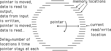
Digital delay systems are constructed from chips originally designed for computer use. These chips contain parallel access circuitry, so the bucket brigade configuration is not used. The memory locations are numbered, and a counting circuit, called a POINTER, controls which location is connected to the A-to-D or the D-to-A. The pointer is designed so it starts over with zero after it hits the highest location, so the whole process is best envisioned as circular:

Fig.2 How a digital delay is organized
Operation of the system is controlled by a complex clock circuit. At each sample time, the location indicated by the pointer is connected to the D-to-A, and the value at that location is read out. Then the same location is connected to the A-to-D and a new value is written in. After that the pointer is moved up one value and the system waits for the next sample time. Since a value will wait in its location until the entire memory has been filled, the delay time is determined by the number of memory locations available. As in the analog delay, minor changes in the clock rate will fine tune the delay time.
Large changes in the delay time can be made by using separate pointers for the read and write functions. When that is done, the delay time is determined by the difference between the two pointers.
There are some interesting tricks that can be done with a digital delay system. For instance, suppose we stop the data writing process but continue to read. The output will be the same series of values over and over, and part of the signal will repeat endlessly. The result is the same as a short tape loop with a splice at the point where the writing stopped. (The quality of the splice is a matter of luck, and generally produces a recurring pop or GLITCH.) Now if you adjust the clock rate, the pitch of the output signal will change, just as it would if you changed the speed of a tape recorder.
The pitch will change any time you adjust the clock in a sampled system. This change is similar to doppler shift, and is caused by the difference between the writing rate and the reading rate. Usually the change is brief, lasting only until the memory is filled with samples taken at the new rate.
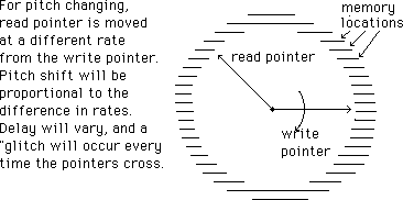
We can make the pitch change work continuously if we start the writing circuit again at the original sampling rate, and continue to read at the changed rate. The delay time will change as the read and write pointers pull away from each other, and there will be a glitch whenever the two pointers cross (most commercial pitch changers perform some simple signal modification to avoid this glitch as much as possible).

Fig 3. Changing pitch
To use a delay as a simple reverberator, we apply a little of the output signal to the input along with the new material. (Any time the output of a device is connected to its own input we have FEEDBACK. Feedback must be carefully controlled- you probably can name examples of uncontrolled feedback.) Then if a short signal is applied to the system, the sound will cycle through the system a few extra times before dying out. If you do this with only one delay the result will be like the reverberation of a rain barrel or shower stall, but it will be reverberation nonetheless. More realistic reverberation can be generated using several delays of different lengths. Delays constructed with reverberation in mind feature multiple outputs and are called TAPPED DELAYS.

Fig 4. A simple reverberator.
Delays can be used to modify the frequency content of a signal. To do this some of the undelayed signal is added to the output of the delay. (This is called FEEDFORWARD.) In the essay on spectral analysis it was noted that if sine waves of equal frequency but different phase are added together, the result is a sine wave of amplitude determined by the phase difference, that amplitude being zero at a difference of 180 degrees. If you mix a complex signal with a delayed version of the same signal, some components of the signal will have the equivalent of a 180 degree phase shift caused by the delay, and will be suppressed. This will happen for any component with a half period equal to an even fraction of the delay time. This means that for any delay time d, there is a frequency F (such that F=1/2d) that will be filtered out of the output. In fact, the entire series F, 2F, 3f... will be missing. If the input is inverted before the combination occurs, F will equal 1/d. This process is called COMB FILTERING, because a graph of the frequency response looks like a comb.

Fig. 5 Comb filter.
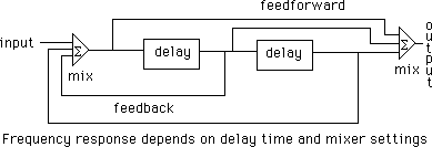
If you build a delay and add both feedforward and feedback, you can construct other kinds of filters. In fact, any kind of filter can be specified by adding multiple delay units and carefully controlling the amounts of feedforward and feedback. The basic unit of a digital filter is called a pole: this example has two of them.

Fig. 6 Digital filter (simplified)
Digital filters are actually programmed in computers rather than built in hardware. The techniques used are a bit advanced for this discussion.
Peter Elsea 1996